Airbus A320 (CFM56/V2500) B1 & B2
- Description
- Curriculum
- Reviews
Introduction:
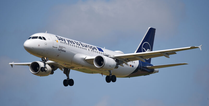
The EASA Part-66 compliant Airbus A320 (CFM56/V2500) B1 & B2 Type Course is tailored to aircraft maintenance engineers seeking to specialize in the Airbus A320 family. This course provides comprehensive training in the maintenance, operation, and troubleshooting of the Airbus A320 equipped with CFM56 and V2500 engines. With a focus on both B1 (mechanical and avionics systems) and B2 (avionics and electrical systems) categories, this program ensures participants are well-prepared to meet the rigorous standards of EASA Part-66 certification.
Course Features:
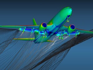
- In-Depth Systems Knowledge: Learn the complete operation and maintenance of Airbus A320 systems, including airframe, powerplant, avionics, electrical, and mechanical components.
- CFM56 and V2500 Engine Expertise: Receive specialized training on the two key engine types used in the A320 family, covering performance, diagnostics, and maintenance procedures.
- B1 & B2 License Preparation: Prepare for EASA Part-66 B1 (mechanical) and B2 (avionics) certification exams with targeted content and practical assessments.
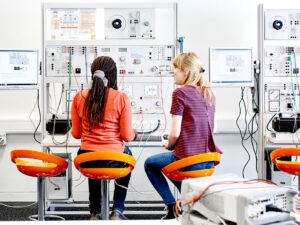
- Practical Hands-On Training: Participate in live maintenance sessions and troubleshooting exercises on Airbus A320 systems, ensuring readiness for real-world scenarios.
- Regulatory Compliance: Ensure compliance with EASA Part-66 standards, focusing on safety, airworthiness, and certification processes required for operating within approved maintenance organizations.
Target Audience:
This course is ideal for aircraft maintenance engineers seeking EASA Part-66 B1 and B2 type ratings for the Airbus A320 family with CFM56 and V2500 engines. It is suited for individuals working in or aspiring to join EASA Part-145 approved maintenance organizations, particularly those specializing in A320 operations. Whether you are an experienced engineer looking to enhance your skillset or a newly licensed professional preparing for type rating certification, this course provides the essential technical and regulatory training required to work on the Airbus A320.
-
21
 21.1 Air Conditioning System Component Location
 -
22
21.2 Zone Temperature Control (Classic)
-
23
21.2.1 Air Conditioning System Presentation
-
24
21.2.2 Air Conditioning System Component Location
-
25
21.2.3 System Presentation
-
26
21.2.4 Pack Presentation
-
27
21.2.5 Flow Control & Pack Components D/O
-
28
21.2.6 Pack Sensors Description / Operation
-
29
21.2.7 Cockpit & Cabin Components D/O
-
30
21.2.8 Zone Temperature Control Interfaces
-
31
21.2.9 Emergency RAM Air Inlet D/O
-
32
21.3 Zone Temperature Control (Enhanced)
-
33
21.3.1 System Presentation
-
34
21.3.2 Pack Presentation
-
35
21.3.3 Flow Control & Pack Components D/O
-
36
21.3.4 Pack Sensors Description/Operation
-
37
21.3.5 Cockpit & Cabin Components
-
38
21.3.6 Zone Temperature Control Interfaces
-
39
21.3.7 Emergency Ram Air Inlet D/O
-
40
21.4 Ventilation (General)
-
41
21.4.1 System Design
-
42
21.4.2 System Presentation
-
43
21.5 Avionics Ventilation
-
44
21.5.1 System Component Location
-
45
21.5.2 System Description and Operation
-
46
21.5.3 System Interfaces
-
47
21.6 Cargo Ventilation
-
48
21.6.1 System Component Location
-
49
21.6.2 Cargo Ventilation & Heating
-
50
21.6.3 System Control
-
51
21.7 Pressurization Control
-
52
21.7.1 System Component Location
-
53
21.7.2 System Presentation
-
54
21.7.3 System Control
-
55
21.8 Air Conditioning Sys - Line Maintenance
-
56
22.1.1 Automatic Flight System Design Philosophy (2)
-
57
22.1.2 Automatic Flight System Presentation
-
58
22.1.3 FAC General (2)
-
59
22.1.4 FMGC General(2)
-
60
22.1.5 Autopilot Presentation (2)
-
61
22.1.6 Flight Director Presentation (2)
-
62
22.1.7 Auto thrust Presentation (2)
-
63
22.1.8 Automatic Flight Sys Control & Indicating (2)
-
64
22.1.9 Automatic Flight Sys Maintenance System D/O (3)
-
65
22.2.1 Yaw Axis Control D/O (3)
-
66
22.2.2 FAC Engagement D/O (3)
-
67
22.2.3 Yaw Damper Function D/O (3)
-
68
22.2.4 Flight Envelope Protection D/O (3)
-
69
22.2.5 FAC Warnings (3)
-
70
22.3.1 Flight Guidance Auto thrust D/O (3)
-
71
22.3.2 Flight Guidance Priority Logic (3)
-
72
22.3.3 Flight Control Unit D/O (3)
-
73
22.4.1 Flight Management Priority Logic (3)
-
74
22.4.2 Flight Planning D/O (3)
-
75
22.4.3 FMGS Warnings (3)
-
76
23-1-1 Communications Level 2
-
77
23-2-1 Radio Management Panel Interfaces
-
78
23-2-2 Audio Switching D/O
-
79
23-2-3 Audio Management Unit Interfaces
-
80
23-2-4 Cockpit Loudspeaker Muting Circuit D/O
-
81
23-2-5 HF System Architecture D/O
-
82
23-2-6 VHF System D/O
-
83
23-2-7 SELCAL and Cockpit Call System D/O
-
84
23-2-8 Flight Interphone System D/O
-
85
23-2-9 Radio Communication D/O
-
86
23-2-10 Static Discharging Presentation
-
87
23-2-11 Speech Communication Warnings
-
88
23-3-1 ACARS Architecture
-
89
23-3-2 ACARS VHF 3 Operation
-
90
23-4-1 MCS SATCOM D/O
-
91
23-5-1 CVR Operational Modes D/O
-
92
23-5-2 CVR Electrical Schematic
-
93
23-6-1 Emergency Locator Transmitter System D/O
-
94
23-7-1 Emergency Locator Transmitter System (Operation)
-
95
23-8-1 CIDS Director/DEU Architecture
-
96
23-8-2 CIDS Director Description/Operation
-
97
23-8-3 CIDS Type A DEU Description/Operation
-
98
23-8-4 CIDS Type B DEU Description/Operation
-
99
23-8-5 CIDS DEU Mount Description
-
100
23-8-6 FAP Pages Presentation
-
101
23-8-7 Attendant Indication Panel (AIP) D/O
-
102
23-8-8 Area Call Panel (ACP) Indications
-
103
23-8-9 Cabin Attendant Handset Presentation
-
104
23-8-10 Passenger Address System Description
-
105
23-8-11 Passenger Address System Operation
-
106
23-8-12 Cabin Interphone System D/O
-
107
23-8-13 Service Interphone D/O
-
108
23-8-14 Passenger Call System D/O
-
109
23-8-15 Passenger Lighted Signs D/O
-
110
23-8-16 Prerecorded Announcement & Boarding Music
-
111
23-8-17 CIDS Evacuation Signalling D/O
-
112
23-8-18 CIDS Warnings
-
113
23-8-19 CIDS Director Interfaces
-
114
23-8-20 FAP & AAP Interfaces
-
115
23-8-21 CIDS Programming
-
116
23-9-1 Passenger Entertainment System Presentation
-
117
23-9-2 Passenger Music Entertainment System D/O
-
118
23-9-3 Video Entertainment System D/O (option)
-
119
23-9-4 PAX Visual Information SYS D/O (option)
-
120
23-9-5 Cabin Management System D/O
-
121
24.1.1 General
-
122
24.1.2 System diagram Description
-
123
24.1.3 Electrical System & Circuit Identification
-
124
24.2.1 IDG Cooling System
-
125
24.2.2 IDG Monitoring
-
126
24.2.3 IDG Drive Part D/O
-
127
24.2.4 IDG Generator Part D/O
-
128
24.2.5 AC Main Generation D/O
-
129
24.2.6 GCU D/O
-
130
24.2.7 AC Auxiliary Generation General Description incomplete
-
131
24.2.8 AC Auxiliary Generation D/O
-
132
24.2.9 External Power Supply General Description
-
133
24.2.10 External Power Supply D/O
-
134
24.2.11 GAPCU D/O
-
135
24.2.12 AC/DC Ground Service Distribution D/O
-
136
24.2.13 Bus Tie Logic D/O
-
137
24.2.14 Galley Supply D/O
-
138
24.2.15 AC Generation Interfaces
-
139
24.3.1 Electrical Power System Line Maintenance
-
140
24.3.2 IDG Removal and Installation
-
141
24.4.1 AC Emergency Generation D/O
-
142
24.4.2 EMER Electrical Power Logic Description
-
143
24.4.3 RAT Activation
-
144
24.4.4 CSM/G GCU D/O & CSM/G Operational Test Electrical Circuit
-
145
24.4.5 Static Inverter Description/Operation
-
146
24.4.6 AC Essential BUS Switching
-
147
24.4.7 Fuel Pumps ELEC PWR Supply in Smoke CONFIG
-
148
24.4.8 AC/DC Sheddable Bus Supply
-
149
24.5.1 Refueling on Battery
-
150
24.6.1 DC Main Generation D/O
-
151
24.6.2 DC Normal/Essential Generation SWTG D/O
-
152
24.6.3 DC Normal/Essential Generation SWTG ELEC
-
153
24.6.4 Transformer Rectifier D/O
-
154
24.6.5 Battery System D/O
-
155
24.6.6 Battery Charge Limiter D/O
-
156
25.1.1 General
-
157
25.2.1 Cockpit Emergency Equipment Presentation
-
158
25.2.2 Cockpit Seats Description / Operation
-
159
25.2.3 Cockpit Escape Rope D/O
-
160
25.2.4 Sliding Window Description / Operation
-
161
25.3.1 Passenger Compartment
-
162
25.3.2 Passenger and Attendant Seats D/O
-
163
25.3.3 Typical Galley Installation
-
164
25.3.4 Typical Lavatory Installation
-
165
25.3.5 Pax Door Escape Slide Deployment / Description
-
166
25.3.6 Passenger Door Escape Slide Disconnection
-
167
25.3.6 Passenger Door Escape Slide Installation
-
168
25.3.7 Pax Door Escape Slide/Raft Deployment/Description
-
169
25.3.8 Pax Door Escape Slide/Raft Disconnection
-
170
25.3.9 Pax Door Escape Slide/Raft Installation
-
171
25.3.10 Off wing Esc Sld Release Mech Description
-
172
25.3.11 Offwing Escape Slide Removal
-
173
25.3.12 Offwing Escape Slide Installation
-
174
25.3.13 Emergency exit escape slide deployment/descr. (A 321)
-
175
25.3.14 Emergency Exit Escape Slide Installation (A321)
-
176
25.4.1 Cargo Loading Operation
-
177
25.4.2 Draining System
-
178
25.4.3 Cargo Compartment Decompression Panel
-
179
25.5.1 Equipment Furnishings Line Maintenance
-
180
25.5.2 Equipment Furnishings Line Maintenance (Maintenance Tips)
-
181
26.1.1 Engine and APU Fire Protection General
-
182
26.2.1 Engine Fire Detection Logic
-
183
26.2.2 Engine Fire Push Button Interfaces
-
184
26.2.3 System Warnings
-
185
26.2.4 System Operation in Case of ENG Fire in Flight
-
186
26.2.5 System Operation in Case of ENG Fire on GND
-
187
26.2.6 Precautions
-
188
26.2.7 Electrical Circuits
-
189
26.3.1 APU Fire Detection Logic
-
190
26.3.2 APU Fire Push Button Interfaces
-
191
26.3.3 APU Fire Detection System Warnings
-
192
26.3.4 System Operation in Case of APU Fire
-
193
26.3.5 Auto Extinguishing on Ground
-
194
26.3.6 Precautions
-
195
26.3.7 Electrical Circuits
-
196
26.4.1 Avionics Smoke Detection
-
197
26.4.2 Avionics Smoke Procedure
-
198
26.5.1 Cargo & Lavatory Fire Protection (Classic)
-
199
26.5.2 Cargo Fire Protection System Presentation
-
200
26.5.3 Cargo & Lavatory Smoke Detection System D/O
-
201
26.5.4 Cargo Smoke Detection Warnings
-
202
26.5.5 Cargo Smoke Procedure
-
203
26.5.6 Lavatory Smoke Detection Warnings
-
204
26.5.7 PTP Pages Presentation for LAV Fire PROT SYS
-
205
26.5.8 Precautions
-
206
26.5.9 Flow Metering System for ETOPS
-
207
26.5.10 System Over View
-
208
26.6.1 Enhanced Smoke Detection System
-
209
26.6.2 Cargo Fire Protection System Presentation
-
210
26.6.3 Cargo & Lavatory Smoke Detection System D/O
-
211
26.6.4 FAP Smoke Detection Page
-
212
26.6.5 Cargo Smoke Detection Warnings
-
213
26.6.6 Cargo Smoke Procedure
-
214
26.6.7 Lavatory Smoke Detection Warnings
-
215
26.6.8 Precautions
-
216
26.6.9 Flow Metering System for ETOPS
-
217
26.7.1 Fire Protection
-
218
27.1.1 Flight Controls Presentation (Introduction)
-
219
27.1.2 Flight Controls System Component Location
-
220
27.2.1 Flight Controls Presentation (Controls)
-
221
27.2.2 Flight Controls Presentation (Indicating)
-
222
27.3.1 General
-
223
27.3.2 Side Stick Description and Operation
-
224
27.4.1 Flight Control Laws
-
225
27.4.2 Mechanical Back.Up
-
226
27.4.3 Principle
-
227
27.4.4 Normal Law
-
228
27.5.1 Roll Control Normal D/O
-
229
27.5.2 Roll Control Abnormal Operation
-
230
27.5.3 Aileron Servo Control Operation
-
231
27.5.4 Speed Brake & Ground Spoiler D/O
-
232
27.5.5 Spoiler Servo Control Operation
-
233
27.5.6 Yaw Control Normal D/O
-
234
27.5.7 Yaw Control Abnormal D/O
-
235
27.5.8 Rudder Trim Actuator D/O
-
236
27.5.9 Rudder Limiter Operation
-
237
27.5.10 Rudder Servo Control Operation
-
238
27.5.11 Yaw Damper Servo Actuator Operation
-
239
27.6.1 Pitch Control Normal D/O
-
240
27.6.2 Pitch Control Abnormal D/O
-
241
27.6.3 Elevator Servo Control Operation
-
242
27.6.4 THS Actuator Operation
-
243
27.7.1 Pilot Orders
-
244
27.7.2 Flight Control Panels
-
245
27.7.3 Hydraulic Pressure
-
246
27.7.4 Rudder Pedal Position
-
247
27.7.5 FMGC
-
248
27.7.6 FAC
-
249
27.7.7 ADIRS
-
250
27.7.8 LGCIU
-
251
27.7.9 SFCC
-
252
27.7.10 RA
-
253
27.7.11 BSCU
-
254
27.7.12 Wheel Tachometer
-
255
27.7.13 Accelerometer
-
256
27.7.14 EFCS Monitor Interface
-
257
27.8.1 Flight Controls System Component Location
-
258
27.8.2 Slats,Flaps Control D/O
-
259
27.8.3 Slats Flaps Abnormal Locking Operation
-
260
27.8.4 Slats Mechanical Drive D/O
-
261
27.8.5 Flaps Mechanical Drive D/O
-
262
27.8.6 Flaps Drive Stations D/O
-
263
27.8.7 Flaps Mechanical Drive D/O (A320)
-
264
27.8.8 Flaps Drive Stations D/O (A320)
-
265
27.8.9 Flaps Attachment Failure Det Description
-
266
27.8.10 SFCC Control Interfaces
-
267
27.8.11 SFCC Monitor Interfaces
-
268
27.9.1 Flight Controls System Line Maintenance
-
269
28.1.1 Fuel System Components Location
-
270
28.1.2 Cockpit System CTL and Indication
-
271
28.1.3 ECAM Page Presentation
-
272
28.1.4 Venting System Description / Operation
-
273
28.1.5 Water Drain Valve Operation
-
274
28.1.6 Engine Feed System D/O
-
275
28.1.7 Fuel IDG Cooling System Presentation Principle
-
276
28.1.8 APU Feed System D/O
-
277
28.1.9 Refuel / Defuel Control Panel Presentation
-
278
28.1.10 Cockpit Preselector Presentation (Option)
-
279
28.1.11 Refuel / Defuel System D/O
-
280
28.1.12 Automatic Refuel Operation
-
281
28.1.13 Fuel Quantity Indicating
-
282
28.1.14 Fuel Quantity Indicating
-
283
28.1.15 Fuel Level Sensing
-
284
28.2.1 Fuel System Component Location
-
285
28.2.2 Fuel Feed System Operation
-
286
28.2.3 Fuel Quantity Indicating
-
287
28.2.4 Fuel Level Sensing
-
288
28.2.5 A321 Fuel Vent System D/O
-
289
28.2.6 A321 Fuel Recirculation System
-
290
28.3.1 ACT System Presentation
-
291
28.3.2 Act Installation Presentation
-
292
28.4.1 Act System Controls and Indicating
-
293
28.4.2 ACT System D/O
-
294
28.4.3 ACT To CTR TK Fuel XFR Operation
-
295
28.4.4 1 ACT To 2 ACTS Differences
-
296
28.5.1 Fuel System Line Maintenance
-
297
29.1.1 Hydraulic Power System Component Location
-
298
29.1.2 Hydraulic System Users
-
299
29.1.3 Circuit Identification and Routing
-
300
29.2.1 Hydraulic Power System Presentation
-
301
29.3.1 Green Hydraulic System D/O
-
302
29.3.2 Blue Hydraulic System D/O
-
303
29.3.3 Yellow Hydraulic System D/O
-
304
29.3.4 Hydraulic Reservoir Pressurizing System D/O
-
305
29.3.5 Hydraulic Reservoir Filling Presentation
-
306
29.3.6 Seal Drain System Description
-
307
29.4.1 Reservoir Depressurization/Pressurization
-
308
29.4.2 Reservoir Filling
-
309
29.4.3 Hydraulic Power System Line Maintenance
-
310
29.4.4 RAT Test
-
311
29.4.5 Hydraulic Leakage
-
312
29.4.6 Leak Measurement System Presentation
-
313
30.1.1 Ice and Rain Prot Systems Presentation
-
314
30.2.1 System Presentation
-
315
30.2.2 Ice and Rain Protection System Component Location
-
316
30.2.3 System Interfaces
-
317
30.3.1 System Presentation
-
318
30.3.2 Ice and Rain Protection System Component Location
-
319
30.3.3 System Interfaces
-
320
30.4.1 System Introduction
-
321
30.4.2 System Presentation
-
322
30.4.3 System Description/Operation
-
323
30.5.1 System Presentation
-
324
30.5.2 System Description/Operation
-
325
30.6.1 System Presentation Classic
-
326
30.6.2 System Presentation Enhanced
-
327
30.7.1 System Presentation
-
328
30.8.1 Potable Water Service Panel Anti.Ice System D/O
-
329
30.8.2 Toilet Service Panel Anti.Ice System D/O
-
330
30.9.1 System Presentation
-
331
30.9.2 Dual Advisory Ice Detection Description/Operation
-
332
30.10.1 Ice and Rain Protection System Line Maintenance
-
333
31.1.1 EIS Architecture
-
334
31.1.2 Engine/Warning Display Presentation
-
335
31.1.3 ECAM Warnings Presentation
-
336
31.1.4 EIS ECAM Normal and Manual Mode Description
-
337
31.1.5 ECAM Advisory & Failure Related Modes
-
338
31.1.6 ECAM Description/Operation
-
339
31.1.7 EFIS Description/Operation
-
340
31.1.8 DMC ARINC Bus Reconfiguration
-
341
31.1.9 EIS Abnormal Operation
-
342
31.2.1 Air Precision Clock
-
343
31.3.1 CFDS Component Location
-
344
31.3.2 CFDS Fault Processing
-
345
31.3.3 CFDS Aircraft System Types
-
346
31.3.4 CFDS Failure Classification
-
347
31.3.5 CFDS Reports
-
348
31.3.6 CFDS Phases
-
349
31.3.7 CFDIU Functions
-
350
31.3.8 Post Flight Report Filtering Function
-
351
31.4.1 Printer Presentation
-
352
31.4.2 Printer Description/Operation
-
353
31.4.3 Printer System Interfaces
-
354
32.1.1 Landing Gear Presentation
-
355
32.1.2 Main Landing Gear Description
-
356
32.1.3 Main Landing Gear Doors Description
-
357
32.1.4 Nose Landing Gear Description
-
358
32.1.5 Nose Landing Gear Doors Description
-
359
32.2.1 Landing Gear System Component Location
-
360
32.2.2 Landing Gear Presentation
-
361
32.2.3 Landing Gear Normal Operation
-
362
32.2.4 Landing Gear Free Fall Extension
-
363
32.2.5 Landing Gear Safety Precautions
-
364
32.2.6 Landing Gear Doors Ground Operation
-
365
32.2.7 Landing Gear Doors Ground Opening D/O
-
366
32.2.8 LGCIU Control Signals
-
367
32.2.9 LGCIU Monitoring Interfaces
-
368
32.3.1 Landing Gear Presentation
-
369
32.3.2 Brake System Description
-
370
32.3.3 Brake Hydraulic System Operation
-
371
32.3.4 Auto.Brake System D/O
-
372
32.3.5 Anti.Skid Function
-
373
32.3.6 Brake Temperature System D/O
-
374
32.3.7 Brake Cooling System D/O (Option)
-
375
32.4.1 Alternate and Parking Brake
-
376
32.4.2 Normal Braking
-
377
32.4.3 Alternate Braking with Anti.Skid
-
378
32.4.4 Alternate Braking without Anti.Skid
-
379
32.4.5 Parking Braking
-
380
32.5.1 Nose Wheel Steering System
-
381
32.5.2 Nose Wheel Steering Components
-
382
32.5.3 Nose Wheel Steering System Operation/Control
-
383
32.6.1 Nose Wheel Steering Enhanced Description and Operation
-
384
32.7.1 BSCU Control Interfaces
-
385
32.7.2 BSCU Architecture & Monitoring Interface
-
386
32.7.3 ABCU Architecture & Monitoring Interface
-
387
32.8.1 TPIS System Description/Operation
-
388
32.9.1 Landing Gear System Line Maintenance
-
389
32.9.2 Wheel and Brake Removal and Installation
-
390
32.9.3 Main Landing Gear Servicing
-
391
32.9.4 Main Landing Gear Shock Absorber Servicing
-
392
33.1.1 General
-
393
33.2.1 Cockpits Lights
-
394
33.2.2 General Cockpit Illumination
-
395
33.2.3 Console Lighting
-
396
33.2.4 Instrument Panel Lighting
-
397
33.2.5 Instrument and Panel Integral Lighting
-
398
33.2.6 Reading Lights
-
399
33.3.1 CKPT Annunciator Light Test & Dimming D/O
-
400
33.3.2 CKPT Annunciator Light Test & Dimming D/O
-
401
33.3.3 Ckpt Annunciator Light Test & Dimming D/O
-
402
33.3.4 Ckpt Annunciator Light Test & Dimming D/O
-
403
33.4.1 Cabin Lights System Description
-
404
33.5.1 Fap Cabin Lighting Page
-
405
33.5.2 Fap Cabin Lighting Page
-
406
33.6.1 Cargo & Service Compartment Lights
-
407
33.6.2 Cargo And Service Compt Light System And Controls Presentation
-
408
33.6.3 Cargo And Service Compt Light System And Controls Presentation
-
409
33.6.4 Cargo And Service Compt Light System And Controls Presentation
-
410
33.7.1 Exterior Lights
-
411
33.8.1 Emergency Lighting
-
412
33.8.2 Seat & Floor Mounted Emer Lights Sys D/O
-
413
33.8.3 Seat & Floor Mounted Emer Lights Sys D/O
-
414
34.1.1 ADIRS Principle
-
415
34.1.2 Air Data Probes Presentation
-
416
34.1.3 ADIRS Switching
-
417
34.1.4 ADIRS Alignment through MCDU
-
418
34.1.5 ADIRS ECAM Warnings
-
419
34.2.1 ISIS D/O
-
420
34.2.2 ISIS Interfaces
-
421
34.2.3 ISIS BITE and Test
-
422
34.3.1 MMR System Presentation
-
423
34.3.2 MMR System Description/Operation
-
424
34.4.1 WXR/PWS System Presentation
-
425
34.4.2 WXR/PWS Description/Operation
-
426
34.4.3 WXR/PWS Operational Precautions
-
427
34.5.1 Radio Altimeter System Presentation
-
428
34.5.2 Radio Altimeter Description/Operation
-
429
34.6.1 TCAS Presentation
-
430
34.6.2 TCAS Description/Operation
-
431
34.7.1 EGPWS Presentation
-
432
34.7.2 EGPWS Description/Operation
-
433
34.7.3 EGPWS Modes
-
434
34.8.1 DME System Presentation
-
435
34.8.2 DME Description/Operation
-
436
34.9.1 ATC System Presentation
-
437
34.9.2 ATC Description/Operation
-
438
34.10.1 ADF System Presentation
-
439
34.10.2 ADF Description/Operation
-
440
34.11.1 VOR/MKR System Presentation
-
441
34.11.2 VOR/MKR Description/Operation
-
442
34.12.1 Navigation System Warnings (Except ADIRS)
-
443
34.13.1 Radio Navigation Frequency Selection
-
444
35.1.1 Oxygen
-
445
35.2.1 Control and Indicating
-
446
35.3.1 Flight Crew Oxygen System
-
447
35.3.2 Crew Oxy Mask Utiliz/Stowage/Tests
-
448
35.4.1 System Overview<p style="text-align: justify"><span style="font-family: arial, helvetica, sans-serif;font-size: 18pt">The masks fall automatically when the cabin altitude is higher than 14,000 feet or manually when a crew member pushes the MASK Manual ON push button. A taped message is transmitted on the passenger address system. </span></p> <p style="text-align: justify"><span style="font-family: arial, helvetica, sans-serif;font-size: 18pt">The passenger System ON indicator light comes on white when the passenger oxygen system is electrically supplied. A reset is available to rearm the electrical system after mask re-stowage. The door can be opened manually with a release tool if there is a failure of the container door opening system. When the Timer RESET push button is pushed, the ON white light of the TMR RESET push button comes on. </span></p> <p style="text-align: justify"><span style="font-family: arial, helvetica, sans-serif;font-size: 18pt">The indicator light SYS ON goes off and the taped announcement stops. On the ground, used chemical oxygen units must be replaced and all masks must be re-stowed. The system is reset when the TMR RESET push button is pushed momentarily on the maintenance panel. Manually operated door stops are installed on the container doors. </span></p> <p style="text-align: justify"><span style="font-family: arial, helvetica, sans-serif;font-size: 18pt">These stops are used to do an operational test of the mask release system. In the test position, because of the stops, the doors will not open fully and the masks will not fall out of the container. </span></p> <img class="aligncenter" src="https://medialibrary.pk/o/4-OXYGEN-ATA-35_029.jpg" /> <p style="text-align: center"><span style="color: #ff0000"><strong><span style="font-family: arial, helvetica, sans-serif;font-size: 14pt">Passenger Overview</span></strong></span></p> <p style="text-align: justify"><strong><span style="font-size: 18pt;font-family: arial, helvetica, sans-serif">Triggering</span></strong></p> <p style="text-align: justify"><span style="font-size: 18pt;font-family: arial, helvetica, sans-serif">In case of rapid cabin depressurization, oxygen masks are automatically dropped to passengers.</span> <span style="font-size: 18pt;font-family: arial, helvetica, sans-serif">Two types of chemical generators are offered which supply oxygen for 15 minutes or 22 minutes.</span></p> <img class="aligncenter" src="https://medialibrary.pk/o/4-OXYGEN-ATA-35_031.jpg" /> <p style="text-align: center"><span style="font-size: 14pt;color: #ff0000"><strong><span style="font-family: arial, helvetica, sans-serif">Triggering</span></strong></span></p> <p style="text-align: justify"><span style="color: #000000;font-size: 18pt"><strong><span style="font-family: arial, helvetica, sans-serif">Automatic Operation</span></strong></span></p> <p style="text-align: justify"><strong><span style="font-family: arial, helvetica, sans-serif;font-size: 18pt">Starting operation</span></strong></p> <p style="text-align: justify"><span style="font-family: arial, helvetica, sans-serif;font-size: 18pt">The system operates automatically when the altitude pressure switch closes. The TIME DELAY RELAYS 8WR and 9WR are electrically supplied. The busbar 401PP supplies 28 VDC to the oxygen power relay 10WR through the time delay relays 8WR and 9WR. </span></p> <p style="text-align: justify"><span style="font-family: arial, helvetica, sans-serif;font-size: 18pt">The busbar 801XP supplies 115 VAC to the electrical latch assemblies of the emergency oxygen containers. The electrical latch assemblies are supplied from separate 115 VAC circuits on opposite sides of the cabin. The emergency-oxygen container doors open and the oxygen masks are released. The relay 10WR energizes the OXYGEN CONTROL RELAY 11WR. From the relay 11WR, the PASSENGER INFORMATION RELAY 19WR is energized. </span></p> <p style="text-align: justify"><span style="font-family: arial, helvetica, sans-serif;font-size: 18pt">A pre-recorded announcement is transmitted over the Passenger Address system. The TIME DELAY RELAY 15WR and the BOARDING ANNUNCIATOR LIGHT TEST & INTERFACE RELAY 6LP are also energized. </span></p> <p style="text-align: justify"><span style="font-family: arial, helvetica, sans-serif;font-size: 18pt">The relay 6LP causes the white SYStem ON light to comes on, the oxygen containers are electrically supplied. 6 seconds after system activation, the TIME DELAY RELAY 25WR is on to interconnect the LH and RH latch assembly electrical circuits. This ensures that all oxygen unit electrical latches remain energized if a circuit is damaged in the event of engine turbine bursting. The time delay relays (8WR and 9WR) operate 30 seconds after the operation of the altitude pressure switch (16WR). They switch off the supply to the oxygen power relay (10WR) and cause the relays 11WR and 25WR to be de-powered and thus the oxygen container solenoids to be de-powered too.</span></p> <img src="https://medialibrary.pk/o/4-OXYGEN-ATA-35_033.jpg" /> <img class="aligncenter" src="https://medialibrary.pk/o/4-OXYGEN-ATA-35_034.jpg" /> <img class="aligncenter" src="https://medialibrary.pk/o/4-OXYGEN-ATA-35_035.jpg" /> <img class="aligncenter" src="https://medialibrary.pk/o/4-OXYGEN-ATA-35_036.jpg" /> <img class="aligncenter" src="https://medialibrary.pk/o/4-OXYGEN-ATA-35_037.jpg" /> <img class="aligncenter" src="https://medialibrary.pk/o/4-OXYGEN-ATA-35_038.jpg" /> <img class="aligncenter" src="https://medialibrary.pk/o/4-OXYGEN-ATA-35_039.jpg" /> <img class="aligncenter" src="https://medialibrary.pk/o/4-OXYGEN-ATA-35_040.jpg" /> <img class="aligncenter" src="https://medialibrary.pk/o/4-OXYGEN-ATA-35_040.jpg" /> <img class="aligncenter" src="https://medialibrary.pk/o/4-OXYGEN-ATA-35_041.jpg" /> <p style="text-align: center"><strong><span style="color: #ff0000;font-size: 14pt;font-family: arial, helvetica, sans-serif">Starting Operation</span></strong></p> <strong><span style="font-family: arial, helvetica, sans-serif;font-size: 18pt">Fault Operation</span></strong> <span style="font-size: 18pt;font-family: arial, helvetica, sans-serif">When the cabin altitude is more than 14.000 ft and relays 8WR and 9WR remain open after the delay of 30 seconds, a failure on the system occurs. The system is in FAULT operation: - relay 15WR (monitoring relays 8WR and 9WR) is operated, - the amber FAULT light comes on, - the SYS white ON light and Passenger Address systems are still on.</span> <img class="aligncenter" src="https://medialibrary.pk/o/4-OXYGEN-ATA-35_043.jpg" /> <img class="aligncenter" src="https://medialibrary.pk/o/4-OXYGEN-ATA-35_044.jpg" /> <p style="text-align: center"><strong><span style="color: #ff0000;font-size: 14pt;font-family: arial, helvetica, sans-serif">Fault Operation</span></strong></p> <p style="text-align: justify"><span style="font-size: 18pt;font-family: arial, helvetica, sans-serif"><strong>Reset Operation</strong> Due to the fault, the Captain or F/O have to press the OXY/TMR RESET P/BSW. The white ON light comes on. The indicator light SYS ON goes off and the taped announcement stops. On ground, used chemical oxygen units must be replaced, all masks stowed and oxygen container doors must be latched closed. The system is reset by momentarily pressing the TMR RESET P/B on the maintenance panel.</span></p> <img class="aligncenter" src="https://medialibrary.pk/o/4-OXYGEN-ATA-35_047.jpg" /> <img class="aligncenter" src="https://medialibrary.pk/o/4-OXYGEN-ATA-35_048.jpg" /> <p style="text-align: center"><strong><span style="color: #ff0000;font-size: 14pt;font-family: arial, helvetica, sans-serif">Reset Operation</span></strong></p> <p style="text-align: justify"><strong><span style="font-family: arial, helvetica, sans-serif;font-size: 18pt">Manual Operation</span></strong> <span style="font-family: arial, helvetica, sans-serif;font-size: 18pt">The passenger oxygen masks may be presented at any time by pressing the MASK MAN ON pushbutton. The white SYS ON light comes on to confirm that the oxygen containers are energized. 6 seconds after system activation, relay 25WR is on to interconnect the LH and RH latch assembly electrical circuits. This ensures that all oxygen unit electrical latches remain energized if a circuit is damaged in the event of engine turbine bursting. Pressing momentarily the TiMeR RESET P/B on the maintenance panel stops the announcement and the indicator light SYS ON goes off.</span></p> <img class="aligncenter" src="https://medialibrary.pk/o/4-OXYGEN-ATA-35_051.jpg" /> <p style="text-align: center"><strong><span style="color: #ff0000;font-size: 14pt;font-family: arial, helvetica, sans-serif">Manual Operation</span></strong></p> <p style="text-align: justify"><strong><span style="font-family: arial, helvetica, sans-serif;font-size: 18pt">Mask Operation</span></strong> <span style="font-family: arial, helvetica, sans-serif;font-size: 18pt">As soon as the emergency oxygen container doors open, the masks fall out. They are hung on lanyards within the reach of users. When the first user pulls the mask towards his face, the release pin starts the chemical generation. Oxygen flows through the flexible supply hoses to all masks of the container. Each flow indicator shows a green stripe.</span></p> <p style="text-align: justify"><strong><span style="font-family: arial, helvetica, sans-serif;font-size: 18pt">Chemical Oxygen Generator</span></strong> <span style="font-family: arial, helvetica, sans-serif;font-size: 18pt">The chemical generator uses the basic principal of thermal decomposition of sodium chlorate. A thermal indicator shows the generator condition. According to the generator type, there can be two different indicators: 1- Black: the oxygen generator has been burned out. - Yellow: the oxygen generator is new. 2- Blue: the oxygen generator has been burned out. - Pink: the oxygen generator is new. The chlorate core is fitted in a stainless steel housing.</span></p> <p style="text-align: justify"><strong><span style="font-family: arial, helvetica, sans-serif;font-size: 18pt">Generator Operation</span></strong></p> <p style="text-align: justify"><span style="font-family: arial, helvetica, sans-serif;font-size: 18pt">By pulling the release pin of the starter assembly the spring loaded firing pin will hit the percussion cap. The heat produced in the percussion cap will then activate the starting powder of the generator.</span></p> <img class="aligncenter" src="https://medialibrary.pk/o/4-OXYGEN-ATA-35_053.jpg" /> <p style="text-align: center"><strong><span style="font-size: 14pt;font-family: arial, helvetica, sans-serif;color: #ff0000">Mask operation ... Generator operation</span></strong></p>
-
449
35.5.1 System Overview
-
450
35.6.1 Oxygen System Line Maintenance
-
451
35.6.2 Maintenance Tips
-
452
35.6.3 Safety Precautions
-
453
36.1.1 Pneumatic System
-
454
36.1.2 Pneumatic Sytem Component Location
-
455
36.2.1 Control and Indications
-
456
36.2.2 Airconditioning Panel Description
-
457
36.2.3 ECAM Bleed Page Description
-
458
36.3.1 Engine Bleed System Description
-
459
36.3.2 APU Bleed Air SPLY/X.Bleed System D/O
-
460
36.3.3 Pneumatic System Operation
-
461
36.3.4 Pneumatic System Component Location
-
462
36.3.5 Pneumatic Leak Detection System D/O
-
463
36.3.6 BMC Interfaces
-
464
36.4.1 Pneumatic System Line Maintenance
-
465
38.1.1 System Overview
-
466
38.2.1 Water and Waste Presentation
-
467
38.2.2 Potable Water System D/O (Classic)
-
468
38.2.3 Potable Water System D/O (Enhanced)
-
469
38.2.4 Potable Water System Controls & Indicating
-
470
38.3.1 Water and Waste Presentation
-
471
38.3.2 Potable Water System Controls & Indicating
-
472
38.4.1 Water/Waste System Component Location
-
473
38.5.1 Water and Waste Presentation
-
474
38.6.1 Toilet System Principle
-
475
38.6.2 Toilet System Description
-
476
38.6.3 Toilet System Controls and Indicating
-
477
38.6.4 Toilet System Monitoring
-
478
38.7.1 Toilet System Principle
-
479
38.7.2 Toilet System Description
-
480
38.7.3 Toilet System Controls & Indicating
-
481
38.7.4 Toilet System Monitoring
-
482
38.8.1 Potable Water System Servicing (A320)
-
483
38.8.2 Toilet System Servicing
-
484
38.8.3 Water/Waste System Line Maintenance
-
485
49.1.1 APU System Overview
-
486
49.1.2 APU Leading Particulars
-
487
49.1.3 APU Basic Description
-
488
49.1.4 APU Fuel Feed System D/O
-
489
49.1.5 APU Ignition & Starting D/O
-
490
49.1.6 APU Fuel System D/O
-
491
49.1.7 APU Oil System D/O
-
492
49.1.8 APU Air System D/O
-
493
49.1.9 APU System Management D/O
-
494
49.1.10 APU Warnings
-
495
49.1.11 ECB Interfaces
-
496
49.1.12 APU Installation Presentation
-
497
49.1.13 APU Drain System Presentation
-
498
49.1.14 APU Level 3
-
499
49.1.15 APU Film Presentation
-
500
49.1.16 COMPT Access Doors Opening & Closing
-
501
49.1.17 APU Removal / Installation
-
502
49.2.1 APU Basic Description
-
503
49.2.2 APU Ignition & Starting D/O
-
504
49.2.3 APU Fuel System D/O
-
505
49.2.4 APU Oil System D/O
-
506
49.2.5 APU Air System D/O
-
507
49.2.6 APU System Management D/O
-
508
49.2.7 APU Warnings
-
509
49.2.8 ECB Interfaces
-
510
49.2.9 APU Drain System Presentation
-
511
49.3.1 APU Basic Description
-
512
49.3.2 APU Ignition & Starting D/O
-
513
49.3.3 APU Fuel System D/O
-
514
49.3.4 APU Oil System D/O
-
515
49.3.5 APU Air System D/O
-
516
49.3.6 APU System Management D/O
-
517
49.3.7 APU Warnings
-
518
49.3.8 ECB Interfaces
-
519
49.3.9 APU Drain System Presentation
-
520
49.3.10 APU Film Presentation
-
521
51.1.1 Reference Axes
-
522
51.1.2 Section Numbers
-
523
51.1.3 Station Numbers
-
524
51.1.4 Zones Numbers
-
525
51.2.1 General
-
526
51.2.2 PASSENGER COMPARTMENT DOORS
-
527
51.2.3 Cargo Compartment Doors
-
528
51.2.4 Access and Service Doors
-
529
51.2.5 Landing Gear Doors
-
530
51.3.1 General
-
531
51.3.2 Nose Forward Fuselage
-
532
51.3.3 Forward Fuselage
-
533
51.3.4 Center Fuselage
-
534
51.3.5 Rear Fuselage A319 & A320
-
535
51.3.6 Rear Fuselage A321 General Arrangement
-
536
51.3.7 Cone/Rear Fuselage
-
537
51.4.1 General
-
538
51.4.2 Pylons General Arrangments
-
539
51.4.3 Pylons Primary Structure – Pylon Box
-
540
51.4.4 Pylons Secondary Structure
-
541
51.5.1 Stabilizers General Arrangement
-
542
51.5.2 Trimmable Horizontal stabilizers
-
543
51.5.3 Elevators – Structure Layout
-
544
51.5.4 Vertical Stabilizer
-
545
51.5.5 Rudder
-
546
51.6.1 General Structure Changes
-
547
51.6.2 Laser Beam Welding
-
548
51.7.1 General
-
549
51.7.2 Cockpit Windows
-
550
51.7.3 Cabin Windows
-
551
51.7.4 Door Windows
-
552
51.8.1 General
-
553
51.8.2 Center Wing Box
-
554
51.8.3 Outer Wing
-
555
51.8.4 Outer Wing Box
-
556
51.8.5 Fixed Leading Edge
-
557
51.8.6 Slats
-
558
51.8.7 Fixed Trailing Edge
-
559
51.8.8 Trailing Edge Devices
-
560
51.9.1 General
-
561
51.9.2 Manual Breakdown
-
562
51.10.1 Introduction
-
563
51.10.2 Identification of the Damage
-
564
51.10.3 Mapping
-
565
51.10.4 Detailed Identification
-
566
51.10.5 Damage Assesment
-
567
51.10.6 Repairs
-
568
52.1.1 Doors System Component Location
-
569
52.2.1 Operation From Inside
-
570
52.2.2 Operation From Outside
-
571
52.2.3 Emergency Opening
-
572
52.2.4 Slide Arming Mechanical Operation
-
573
52.2.5 Structure Description
-
574
52.2.6 Locking Mechanism Description
-
575
52.2.7 Esc Slide/Raft Control Mechanism Desc
-
576
52.2.8 Damper/Emergency Cylinder Description
-
577
52.3.1 Doors operation
-
578
52.3.2 Doors Opening For Maintenance
-
579
52.3.3 Doors Structure Description
-
580
52.3.4 Locking Mechanism Description
-
581
52.4.1 Doors Operation
-
582
52.4.2 Doors Structure Description
-
583
52.4.3 Locking Mechanism Description
-
584
52.5.1 Normal Operation
-
585
52.5.2 Manual Operation
-
586
52.5.3 Bulk Cargo Door Operation (A320/A321)
-
587
52.5.4 FWD & AFT Cargo Door Structure Description
-
588
52.5.5 FWD & AFT Cargo Door Locking MECH D/O
-
589
52.5.6 Hydraulic System D/O
-
590
52.5.7 Hydraulic Actuator D/O
-
591
52.6.1 Cockpit Door Operation
-
592
52.6.2 Cockpit Door D/O
-
593
52.7.1 Doors Indication & Warning D/O
-
594
52.8.1 Servicing
-
595
52.8.2 Maintenance Tips
-
596
70.1.1 General
-
597
70.1.2 Engine Characteristics
-
598
70.1.3 Power Plant System Component Location
-
599
70.1.4 Power Plant Drain Presentation
-
600
70.1.5 Air Intake Duct
-
601
70.2.1 Engine System D/O
-
602
70.3.1 Exhaust
-
603
70.3.2 Thrust Reverser System
-
604
70.3.3 Thrust Reverser Management
-
605
70.3.4 Thrust Reverser System D/O
-
606
70.4.1 Engine Bearings & Seals
-
607
70.4.2 Oil System D/O
-
608
70.5.1 Engine Fuel System D/O
-
609
70.5.2 Fuel Return Valve D/O
-
610
70.6.1 FADEC Presentation
-
611
70.6.2 FADEC Architecture
-
612
70.6.3 Fadec Principle
-
613
70.6.4 Ecu Interfaces
-
614
70.6.5 Eiu Interfaces
-
615
70.6.6 EEC Electrical Power Supply Control
-
616
70.7.1 Air System Description/Operation
-
617
70.8.1 Ignition & Starting System Presentation
-
618
70.8.2 Ignition & Starting System D/O
-
619
70A.9.1 Engine Thrust Management
-
620
70.9.2 Throttle Control System D/O
-
621
70.10.1 Engine Monitoring D/O
-
622
70.11.1 Engine Crank
-
623
70.11.2 Start Failure
-
624
70.11.3 Power Plant Installation D/O
-
625
70.11.4 Opening & Closing Of Engine Cowl Doors
-
626
70.11.5 Thrust Reverser Deactivation & Lockout
-
627
70.11.6 Power Plant System Line Maintenance
-
628
70.11.7 Manual Operation Of T/R Pivoting Door
-
629
70.11.8 Engine Removal And Installation Overview
-
630
70.1.1 Introduction
-
631
70.1.2 Engine Characteristics
-
632
70.1.3 Air Intake Cowl
-
633
70.2.1 Engine Modules
-
634
70.2.2 Engine System D/O
-
635
70.3.1 Exhaust
-
636
70.3.2 Thrust Reverser System
-
637
70.3.3 Thrust Reversal Management
-
638
70.3.4 Thrust Reversal System D/O
-
639
70.4.1 Engine Main Bearings& Seals
-
640
70.4.2 Oil System D/O
-
641
70.5.1 Fuels
-
642
70.5.2 Engine Fuel System
-
643
70.5.3 Heat Management System D/O
-
644
70.6.1 FADEC Presentation
-
645
70.6.2 FADEC Architecture
-
646
70.6.3 FADEC Principle
-
647
70.6.4 EEC Interfaces
-
648
70.6.5 EIU Interfaces
-
649
70.6.6 EEC Electrical Power Supply Control
-
650
70.7.1 Air System D/O
-
651
70.8.1 Ignition & Starting System Presentation
-
652
70.8.2 Ignition & Starting System D/O
-
653
70.9.1 Engine Thrust Management
-
654
70.9.2 Engine Press Raising & Shut.Off Valve Control
-
655
70.9.3 Engine LP Fuel Shut.Off Valve Control
-
656
70.9.4 Engine Warnings
-
657
70.10.1 Engine Indicating Presentation
-
658
70.11.1 Engine Crank
-
659
70.11.2 Start Failures
-
660
70.11.3 Power Plant Checks
-
661
70.11.4 Power Plant Installation D/O
-
662
70.11.5 Opening & Closing of Engine Cowl Doors
-
663
70.11.6 Thrust Reverser Deactivation & Lockout
-
664
70.11.7 Manual Operation of T/R Sleeves
-
665
70.11.8 Engine Removal and Installation
-
666
70.11.9 Engine Storage and Preservation
-
667
70.11.10 Power Plant Drain Presentation